
7 Tips for Choosing Industrial Water Meters
Choosing the right Industrial Water Meters can protect production, reduce waste, and expose hidden process losses. The decision is rarely as simple as comparing pipe sizes or purchase prices. Flow range, water quality, pressure, temperature, installation space, and data requirements all influence performance.
A small mistake matters.
A meter installed near a pump may record unstable flow. Sediment can damage sensitive components. Poor grounding can weaken electromagnetic readings. These details are easy to overlook during a busy plant upgrade. Water-metering researcher Dr. Steven Buchberger has described the meter as “the cash register of the water utility.” His point applies to factories too: unreliable measurement can distort costs, maintenance plans, and sustainability reports.
This guide presents seven practical tips for choosing Industrial Water Meters. It considers accuracy at low and high flow rates, meter technology, pipe conditions, pressure loss, calibration, communication systems, and lifecycle support. Ultrasonic meters may suit clean water and flexible installations. Electromagnetic models can handle conductive liquids without moving parts. Mechanical meters remain useful, but they may require more maintenance in harsh environments.
The cheapest option may not be the most economical.
Real facilities are imperfect. Pipes may vibrate, flow may be intermittent, and installation records may be incomplete. A careful selection process should acknowledge these problems instead of hiding them. Review the application with operators, maintenance staff, and qualified suppliers. Ask how the meter will behave on an ordinary Tuesday, not only in ideal laboratory conditions. Reliable data begins with a realistic understanding of the site.
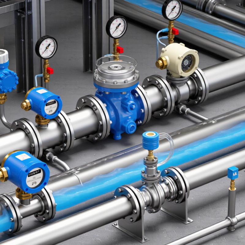
Define Flow Conditions: Size for Peak Rates and a 10:1 Turndown Range
Tip: Define the real flow profile before selecting an industrial water meter. Record normal, minimum, and peak rates during production changes, cleaning cycles, and shutdowns. Peak flow determines the meter’s upper capacity, but low flow tests its usefulness. A 10:1 turndown range means the meter can measure peak flow at ten times the minimum flow. For example, a 100 m³/h peak requires reliable measurement near 10 m³/h. Do not assume this range applies equally across every operating condition.
Tip: Size for stable measurement, not simply for the largest pipe. An oversized meter may struggle when demand falls, causing weak resolution and inconsistent readings. An undersized meter can create excessive pressure loss during peak demand. Check the manufacturer’s flow curves, approved velocity limits, and expected pressure drop. Short answer: measure reality. Temporary clamp-on testing or logged pump data can reveal patterns that design drawings miss.
Tip: Review installation conditions before approving the final size. Confirm straight pipe requirements, valve locations, air pockets, and possible flow disturbances. A carefully selected meter may still perform poorly after a nearby elbow or partially closed valve. I have seen clean calculations fail because actual flow was much lower than estimated. That mistake is worth challenging. Use a calibrated reference instrument when possible, and document the lowest dependable flow, not just the advertised turndown ratio.
