
China Best AOC Fiber Cable for Global Buyers?
Global buyers comparing China’s Aoc Fiber Cable suppliers need more than a low quoted price. They need a product that fits the link, works with the intended equipment, and arrives with clear technical documentation. An active optical cable combines optical fiber with transceivers at both ends, creating a practical option for short, high-speed connections in data centers and other controlled environments. But “compatible” is not always as simple as a product page suggests.
Start with the details that can be checked: supported data rate, cable length, connector type, power requirements, and the equipment’s compatibility list. Ask for datasheets and sample testing when a deployment depends on stable performance. A cable that works in one switch may not behave identically in another. Small differences matter. Buyers should also review factory quality controls, traceability, packaging, warranty terms, and the supplier’s response process for faults. These points are less exciting than a headline price, yet they often shape the real cost of ownership.
China has a broad supplier base, including manufacturers serving enterprise and cloud infrastructure projects. Still, country of origin alone does not prove quality. Request evidence, compare like-for-like specifications, and confirm lead times in writing. A careful buyer may find that the cheapest offer is not the best value—or that a premium quote offers little extra. There is no universal winner. This guide explores how global buyers can assess Aoc Fiber Cable options, ask sharper questions, and make a decision grounded in their own network requirements. Even a thorough checklist cannot remove every uncertainty, so leave room for a pilot order.
What Is an AOC Fiber Cable and How Does It Work?
China Best AOC Fiber Cable for Global Buyers?
What Is an AOC Fiber Cable and How Does It Work?
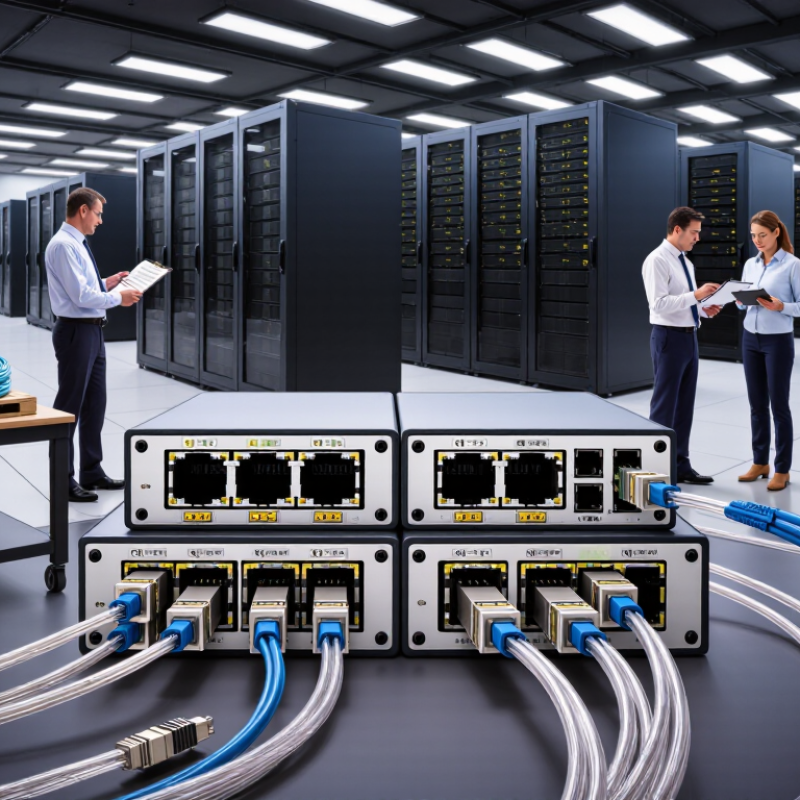
An AOC, or Active Optical Cable, combines optical fiber with electronic transceivers. One connector converts electrical signals into optical signals. The fiber carries light pulses between devices. The opposite connector changes those pulses back into electrical data. This process supports high-speed communication across servers, switches, storage systems, and computing equipment. Unlike passive copper cables, AOCs reduce electromagnetic interference and usually weigh less. They also maintain signal quality across longer rack connections.
In practical installations, cable length and connector type matter greatly. An AOC is factory-terminated, so technicians cannot normally repair or re-terminate it onsite. Check the device interface, transmission speed, operating temperature, and supported protocols before purchasing. I have seen projects fail because teams measured the rack distance too casually. A small routing mistake caused excessive bending near the cabinet door. The cable worked during testing, but installation pressure later affected reliability. That detail is easy to overlook.
Tips: Leave gentle loops instead of sharp bends. Confirm both ends match the equipment. Review the datasheet, insertion loss, power requirements, and compliance information. Test every cable under realistic traffic before deployment. An optical tester can reveal problems that visual inspection misses. Buyers should also request traceable quality records and clear warranty terms. AOC technology is efficient, but it is not universal. Careful matching remains essential.
